Construction
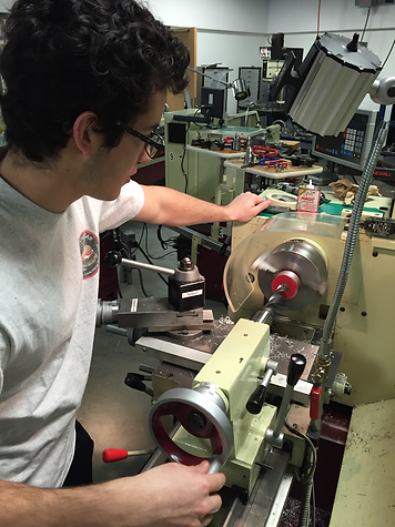
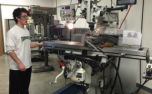
The complete construction of this project was done in the machine shop in Hogue Hall provided by the MET staff. The material was purchased from McMasterCarr.com. The material was then sent to the school where the creator picked it up. Each part needed to be machined to some degree in the machine shop. The construction of this project was taken in a very careful manner. It was very important too. Some of the material came late so the construction was pushed back farther than originally planned.
All of the construction for the project was done in the machine shop in Hogue Hall provided by the MET staff. The rope attachment, bottom and top tower attachments, housing, and spring cap were constructed on a manual milling machine. These were all simple jobs that included milling to the right lengths, machining the step for the rope attachment or boring out the right size hole for the top and bottom tower attachments. The spring cap was completed on a lathe. This inly needed a simple hole to be drilled through it. The spring was cut with a saw.
After each part was machined in the machine shop, various bolts, nuts and screws put it together. Some of the parts did not end up with the best dimensions because of some error from the creator. However, the assembly still came together successfully.
Description
Each part of the project was done in the machine shop in Hogue Hall provided by the MET staff. Each part was done in a different manner. Although most of it was done on the same machine.
This project was done with a few different kinds of material. Aluminum was the material chosen for the top and bottom tower attachments. The housing was made out of stainless steel and the rope attachment was made out of alloy steel. Different materials were chosen to try and keep the device as light as possible. Though the parts that were chosen stainless or alloy steel needed to be as strong as possible instead of light.
Manufacturing Issues
There were a few issues when trying to manufacture the device. For one, some of the material came in different sizes than advertised from McMasterCarr. The spring cap came in a longer length than what was ordered. Therefore, the length had to be turned down to the length that was planned for.
Another issue was dealing with the stainless steel housing. Stainless steel turned out to be a very hard material to work with in the machine shop. This is because the material hardens with heat. Therefore, when trying to drill into the material, it seemed to harden each time a little bit was taken off. Some help was needed from Matt Burvee to help explain how to correctly and effectively drill through the material. Milling this material for the length also was not an easy task because of the same reason. Since the material was also hollow tubing, the machining process was very loud and had to be taken slowly.
One issue found for the top and bottom attachments was figuring out how to correctly cut the hole needed for these parts. An original plan was to buy a ball mill that was big enough to cut these holes. However, a big enough ball mill was not found at a decent enough price. Therefore the plan had to change. Ted Bramble helped figure out a new idea by bolting together the top and bottom attachments and putting them both in a vice on a manual milling machine. A boring bar was then used to bore out the right size hole for the two attachments at the same time. This ended up being very effective because then the holes would line up with each other when put together.
One final issue came when trying to put the assembly together. The top attachment was not sitting inside the housing quite right. This is because the inside of the housing was rounded instead of having sharp corners like originally planned. The material just came like this. Therefore, a file was taken to the edges of the top attachment that would sit in the housing. These edges were ground down until the top attachment sat flat in the housing.
Discussion of Assembly
After figuring out the manufacturing issues, the assembly was able to come together correctly. Each part came together into one final assembly with no sub-assemblies. There was really no issue when putting the parts together into the assembly. Everything fit as it was supposed to.
The first and most important part of the assembly started with the top and bottom tower attachments. This is the most important part because it is where and how this device will attach to the tower of the boat. The holes needed to be the right size so that it would fit around the tower, but also not be too big so that it moves too much. On the inside of the top and bottom tower attachments was a very important piece of foam. This foam will allow the device to not scratch the tower of the boat. This is important because boat owners like to keep their things nice and shiny. If the device were to damage the towers then it would end up not being bought by consumers. This foam would also keep the device from moving too much.
The next part of the assembly is the housing. This housing will be attached in between the two tower attachments. The housing is where all of the rest of the device will be located. It is where the spring, pin, rope attachment, and spring cap will hold itself together. Since this piece was so important, stainless steel was chosen for its strength and resistance to corroding. The housing also has a piece of foam at the bottom of it to keep from scratching the rest of the device.
After attaching the top and bottom attachment with the housing, the spring can then be inserted through the top hole of the housing. The spring will sit on the top of the top attachment inside the housing. The spring will then be capped by the spring cap at the top of the housing. The spring cap will be held by five bolts through the cap and housing and will be held at the bottom of the bolts with nuts on each bolt
Then the rope attachment can be attached to the assembly. The pin is slid through the housing, through the hole in the rope attachment, and through to the other side of the housing. This pin the what the rope attachment piece will rotate about to raise and lower the flag. The pin is a press fit into the housing while it is a clearance fit for the rope attachment. The pin needs to stay in the housing and not slide back and forth. Therefore, it needs to be tight. Since the rope attachment will rotate back and forth, it needs to be a clearance fit.
Finally, the last part of the assembly is attaching the hook to the rope attachment piece. There are two holes in the rope attachment where the rope hook will fit through. Then two nuts will keep the rope hook from leaving the rope attachment. The towing rope will attach to the towing hook which rotates the rope attachment down to react with the spring inside the housing.
